Don't have an account?
Creating an account has many benefits: check out faster, keep more than one address, track orders and more.
Or
Checkout as a Guest
Place your order without creating an account for extra convenience.
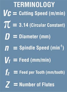
Speeds & Feeds Made Easy!


Contents
- What is the difference between RPM and surface speed?
- How are feed rates measured or expressed?
- Slotting example
- Shouldering example
- What is meant by depth of cut?
- How do I work out my width & depth of cut?
- How do I work out RPM from m/min (Surface speed in metres per minute)?
- How do I calculate feed rate from feed per tooth?
A common query often raised pertains to the calculation of speeds and feeds in machining processes. While our website offers valuable insights into this subject, determining the optimal RPM and feed per tooth isn't always straightforward. Certain cutting data presents surface speed in meters per minute instead of the required RPM, and vice versa. Understanding the methodology behind computing speeds and feeds streamlines the process significantly.
What is the difference between RPM and surface speed?
In simple terms, RPM is the number of revolutions per minute i.e. how many times something rotates per minute. RPM differs based upon the diameter of the tool: smaller tools rotate faster; bigger tools rotate slower.
Surface speed is given in meters per minute. This is the speed (or velocity) that the cutting edge is travelling at as the tool rotates. Surface speed is generally constant regardless of the diameter.
How are feed rates measured or expressed?
Feed rate is the velocity at which the cutter is fed against the workpiece.
It is expressed in units of distance per revolution. It can be expressed thus for milling also, but it is often expressed in units of distance per time for milling (typically millimetres per minute), with considerations of how many teeth (or flutes) the cutter has then determined what that means for each tooth.
Feed rate is dependent on the:
- Type of Tool: Type of Tool (for example a high feed tool like HRM Double may feed at 1.6mm per tooth, whereas a traditional 90 degree mill like Alpha Mill may have a feed rate of just 0.25mm per tooth).
- Depth of Cut: Depth of Cut (for example a high feed tool like HRM Double may have a small depth of cut at just 1mm, whereas a traditional 90 degree mill like Alpha Mill may have a large depth of cut of 8mm).
- Surface finish desired.
- Power available at the spindle: Power available at the spindle (to prevent stalling of the cutter or workpiece).
- Ability of the tooling setup to mitigate vibrations.
- Material characteristics & hardness: Chip flow depends on material type and feed rate. Ideally, chips should be small and are removed early, reducing the heat levels of the tool and workpiece.
Feed rate is the velocity at which the cutter is fed against the workpiece.
It is expressed in units of distance per revolution. It can be expressed thus for milling also, but it is often expressed in units of distance per time for milling (typically millimetres per minute), with considerations of how many teeth (or flutes) the cutter has then determined what that means for each tooth.
Calculating feed rates for single-point cutting tools is fairly simple, largely due to the work being concentrated at one point (or tooth). With a milling machine where multi-tipped/multi-fluted cutting tools are involved, then the desired feed rate becomes dependent on the number of teeth on the cutter.
When you have a larger number of available cutting edges, the feed rates you can use the tool at also increases. However, more teeth and higher feed rates can cause vibration, so a balance should be aimed for.
Slotting example
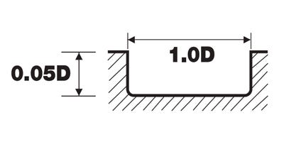
In the picture to the right, we can see that the recommended width of the slot would be 1 x D, or 1 time’s diameter & the recommended depth is 0.5 x D, or half times diameter of the selected cutter.
So, if we imagine the selected cutter to be 10mm, the equation would be:
10 x 0.5 = 5 ∴ the Depth of cut would equal 5mm.
Shouldering example
In the picture to the right, we can see that the recommended depth would be 1 x D, or 1 time’s diameter & the recommended side cut (or stepover) is 0.5 x D, or half times diameter of the selected cutter.
So, if we imagine the selected cutter to be 10mm again, the equation would be:
10 x 0.5 = 5 ∴ the Depth of cut on the side cut would equal 5mm, with a depth of 10mm.
What is meant by depth of cut?
Depth of cut (or DOC) is reference to the amount of material that can be removed from a work piece per pass. These depths vary with every cutter, with some cutters taking small cuts at high speed & others taking full cutter flute length/diameter cuts. The width of cut is taken when slotting (unless trochoidal milling a larger slot with a smaller cutter). The manufacturer recommended values for both depth and width of cut can be found under the “Technical Information” tab on our website, or in the resources section.
How do I work out my width & depth of cut?
Once we have the recommended DOC, the equation is quite simple!
VC = surface speed in metres a minute (you can find this in the cutting data, if a range is given e.g. 80-120, always start in the middle).
π (pi) = 3.142.
D = cutting tool diameter.
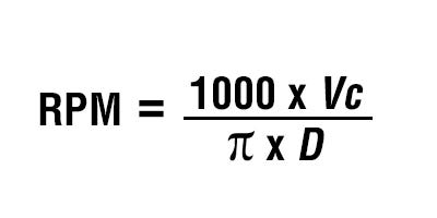
Step by step…
1. Multiply surface speed (metres per minute) by 1000 (e.g. 100 x 1000 = 100,000)
2. Work out pi (3.142) x diameter (e.g. 10 x 3.142 = 31.42)
3. Divide step 1 by step 2 (e.g. 100,000 / 31.42 = 3,182 RPM)
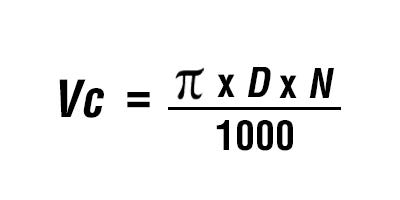
How do I work out RPM from m/min (Surface speed in metres per minute)?
VC = Surface Speed
π (pi) = 3.142
D = Work Piece Diameter
Step by step…
1.Multiply pi (3.142) by Workpiece Diameter by spindle speed (e.g. π x 50 x 2000 = 314159 (rounded))
2.Divide answer by 1000 e.g. 314159(rounded) ÷ 1000 = 314(rounded)
3.∴ VC = 314
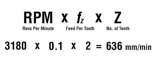
How do I calculate feed rate from feed per tooth?
Once we have established the RPM, we can use this to work out the recommended feed rate. If we use the RPM from the above example (3,180) & establish the recommended feed per tooth (Fz) from the manufacturer, we can work out the velocity at which the cutter is fed against the workpiece in millimetres per minute. For this example, let us use a feed per tooth of 0.10mm and imagine the cutter to have 2 teeth (or flutes).
The equation we need is below, along with an example calculation:
How do I calculate feed rate from mm per rev?
To find the Surface Speed from RPM, we need to follow the equation example below.
IMAGE IS MISSING IN ORIGINAL BLOG